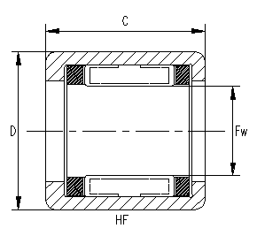
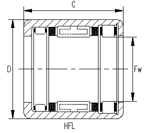
CYJ-- Needle Roller Clutch with Pressed Outer Ring (unilateral bearing) can be treated as converter, non-return device, free wheel device. HF (Needle Roller Clutch): it is made of pressed outer ring and plastic holder; the holder can be installed with plastic reed or the stainless steel reed to guide the needle rollers, bevel race way and needle rollers can be treated as locking device. HFL(Clutch and Bearing Unit): pedestal bearing is installed at the two sides of the needle roller clutch and bears the radial load, the needle roller and the plastic holder units can be treated as the pedestal bearing.
Main Structure Style£º
Bearing No.
Characteristics of Structure
HF
Needle Roller Clutch with Pressed Outer Ring and Steel Spring
HF..KF
Needle Roller Clutch and Bearing Units with Pressed Outer Ring and Plastic Spring
HF..R
Needle Roller Clutch with Pressed Outer Ring and Steel Spring, Knurling Outer Ring
HF..KFR
Needle Roller Clutch and Bearing Units with Pressed Outer Ring and Plastic Spring, Knurling Outer Ring
HFL
Needle Roller Clutch and Bearing Units with Pressed Outer Ring and Steel Spring, Sliding Bearing or Rolling Bearing
HFL..KF
Needle Roller Clutch and Bearing Units with Pressed Outer Ring and Plastic Spring, Sliding Bearing or Rolling Bearing
HFL..R

Needle Roller Clutch and Bearing Units with Pressed Outer Ring and Steel Spring, Knurling Outer Ring

HFL..KFR
Needle Roller Clutch and Bearing Units with Pressed Outer Ring and Plastic Spring, Knurling Outer Ring
Shaft Diameter Clutch Designation Mass Approx
Borndary Dimensions
Torgue Ma Limiting Speed Suitable Drawn Cup Bearings
Plastic Springs Steel Springs Fw D C Rotating Shaft Min-1 Rotatng Outer Ring Min-1
mm g mm Nm rpm
HFSeries ( INA/According to natrium company )
3 HF0306KF   0.9 3 6.5 6 0.2 36000 7000 HK0306TN
4 HF0406KF -- 1 4 8 6 0.34 34000 8000 HK0408TN
HF0406KFR -- 1 4 8 6 0.1 34000 8000 HK0408TN
6 HF0608KF 2.8 6 10 8 1.5 20000 11000 HK0608
HF0612KF HF0612 3 6 10 12 1.76 23000 13000 HK0608
HF0612KFR HF0612R 3 6 10 12 1.76 23000 13000 HK0608
HF061210 3.5 6 12 10 3 20000 13000 HK061208
8 HF0812KF HF0812 3.5 8 12 12 3.15 17000 12000 HK0808
HF0812KFR HF0812R 3.5 8 12 12 4 17000 12000 HK0808
-- HF061210 3.2 8 12 10 3 16000 12000 HK0808
-- HF081410 3.6 8 14 10 4.6 15000 11000 HK081410
-- HF081610 4.1 8 16 10 5.5 15000 11000 HK081610
-- HF081412 4 8 14 12 5 16000 12000 HK081410
10 HF1012KF HF1012 4 10 14 12 5.3 14000 11000 HK1010
HF1012KFR HF1012R 4 10 14 12 1.5 14000 11000 HK1010
12 -- HF1216 11 12 18 16 12.2 11000 8000 HK1212
14 -- HF1416 13 14 20 16 17.3 9500 8000 HK1412
16 -- HF1616 14 16 22 16 20.5 8500 7500 HK1612
18 -- HF1816 16 18 24 16 24.1 7500 7500 HK1812
20 -- HF2016 17 20 26 16 28.5 7000 6500 HK2010
25 -- HF2520 30 25 32 20 66 5500 5500 HK2512
30 -- HF3020 36 30 37 20 90 4500 4500 HK3012
35 -- HF3520 40 35 42 20 121 3900 3900 HK3512

note1£ºUnidirectional bearing''s Maintains frame all is Nylon material £»KF means the Reeds on Maintains frame are Nylon material£¬without KF means the Reeds are Stainless steel
note2£ºR means bearing addendum circle knurling to increases nips the joint effort;
Shaft Diameter Clutch Designation Mass Approx Borndary Dimensions Torgue Ma Limiting Speed Basic Load Ratings
Plastic Springs Steel Springs Fw D C Rotating Shaft Min-1 Rotatng Outer Ring Min-1 C Co
KN
mm g mm Nm rpm
HFL ( INA )
3 HFL0308 -- 3 3 3.6 8 1 -- -- -- --
4 HFL0408 -- 3.5 4 8 8 1.5 -- -- -- --
6 HFL0615KF HFK0615 4 6 10 15 1.76 23000 13000 -- --
HFL0615KFR HFL0615R 4 6 10 15 0.5 23000 13000 -- --
-- HFL061012K 5 6 10 12 -- 21000 12000 -- --
8 -- HFL081212K 6 8 12 12 -- 20000 12000 -- --
-- HFL081412K 7 8 14 12 -- 19000 12000 -- --
HFL0822KF HFL0822 7 8 12 22 3.15 17000 12000 4.05 4.15
HFL0822KFR HFL0822R 7 8 12 22 1 17000 12000 -- --
10 HFL1022KF HFL1022 8 10 14 22 5.3 14000 11000 4.3 4.65
HFL1022KFR HFL1022R 8 10 14 22 1.5 14000 11000 -- --
12 -- HFL1226 18 12 18 26 12.2 11000 8000 6.3 6.5
14 -- HFL1426 20 14 20 26 17.3 9500 8000 7.1 7.7
16 -- HFL1626 22 16 22 26 20.5 8500 7500 7.7 9
18 -- HFL1826 25 18 24 26 24.1 7500 7500 8.3 10.3
20 -- HFL2026 27 20 26 26 28.5 7000 6500 8.9 11.5
25 -- HFL2530 44 25 32 30 66 5500 5500 10.9 14.1
30 -- HFL3030 51 30 37 30 90 4500 4500 12.6 17.6
35 -- HFL3530 58 35 42 30 121 3900 3900 13 19.3

type   Main dimension
Fw D C  
Torrington & NSK
FC4K 1 4 8 6 0.34
FC6 3 6 10 12 1.76
FC6K 3 6 10 12 1.76
FC8 4 8 14 12 5.3
FCL8K 3.5 8 12 12 5
FC10 4.8 10 16 12 6
FCL10K 4 10 14 12 5.3
FC12 11 12 18 16 12.2
FC14K 13 14 20 16 17.3
FC16 14 16 22 16 20.5
FC20 17 20 26 16 28.5
FC25 30 25 32 20 66
FC30 36 30 37 20 90
FC35 40 35 42 20 121
FCB8 10 14 14 20 5
FCB10 15 16 16 20 10
FCB12 18 18 18 26 12.2
FCB16 22 22 22 26 20.5
FCB20 27 26 26 26 28.5
FCB25 44 32 32 30 66
FCB30 51 37 37 30 90
FCB35 58 42 42 30 121

type   Main dimension
Fw D C  
Torrington & NSK
RC040708 3.5 6.35 11.112 12.7 1.9
RC040708-FS 3.5 6.35 11.112 12.7 1.9
RC061008 4.7 9.525 15.875 12.7 4.83
RC061008-FC 4.7 9.525 15.875 12.7 4.83
RC081208 9.2 12.7 19.05 12.7 7.9
RC081208-FS 9.2 12.7 19.05 12.7 7.9
RC101410 14.5 15.875 22.225 15.88 15.4
RC101410-FC 14.5 15.875 22.225 15.88 15.4
RC121610 17 19.05 25.4 15.88 20.9
RC121610-FS 17 19.05 25.4 15.88 20.9
RC162110 16.2 25.4 33.338 15.88 45
RC162110-FC 16.2 25.4 33.338 15.88 45
RCB061014 12 9.525 15.875 22.22 4.83
RCB061014-FS 12 9.525 15.875 22.22 4.83
RCB081214 16 12.7 19.05 22.22 7.9
RCB081214-FC 16 12.7 19.05 22.22 7.9
RCB101416 21.3 15.875 22.225 25.4 15.4
RCB101416-FS 21.3 15.875 22.225 25.4 15.4
RCB121616 26.5 19.05 25.4 25.4 20.9
RCB121616-FC 26.5 19.05 25.4 25.4 20.9
RCB162117 44.8 25.4 33.338 26.99 45
RCB162117-FS 44.8 25.4 33.338 26.99 45


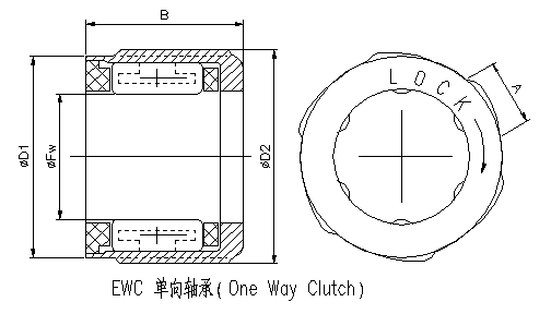
shaft dia. d boundary dimensions torque capacity
Fw D1 D2 B A
mm mm N.m Kg.cm
4 4 8 8.4 6 2.6 0.08 0.82
4 8 8.4 6 2.6 0.15 1.53
6 6 10 10.4 8 2.8 0.25 2.55
6 10 10.4 8 2.8 0.44 4.49
6 10 10.4 8 2.8 0.44 4.49
6 10 10.4 12 2.8 0.88 8.98
8 8 12 12.4 9 2.6 0.49 5
8 12 12.4 9 2.6 0.88 8.98
8 14.2 15 12 3.6 1.18 12.04
8 14.2 15 12 3.6 1.96 20
8 14.2 15 12 3.6 1.96 20
8 14.2 15 14.5 3.6 2.65 27.04
10 10 16 17 10 5 1.18 12.04
10 16 17 10 5 1.96 20
10 16 17 12 5 1.37 13.98
10 16 17 12 5 2.35 23.98
10 16 17 12 5 2.35 23.98
12 12 18 19 16 5.1 6.28 64.08

In order to make Roller pin in Is in as necessary locks the position £¬Maintains the frame to have the stainless steel reed¡£
Limit rotational speed are Effective on Fat and oil lubrication,Width deviation -0mm¡«-0.25mm, special request When ordering explained.

¡¾Print¡¿ ¡¾Back¡¿